Motor Control Center Panel |Power Control Center Panel |PCC Panel |Power Distribution Panel |Main LT Power Panel |Main LT Panel |DG Synchronization panel |Load Management Panel |AMF Cum Synchronization Panel |DG Syn Panel |Paralleling Panel |Hybrid Paralleling Panel |Auto Mains Failure Panel |AMF Panel |AMF ATS Panel |Power Factor Compensation |Passive Filter |Power Factor Correction |APFCR Panel |APFC Panel |Solar ACDB Panel |Solar DCDB Panel |Solar Distribution Panel |Solar ACDB Combiner Panel |Solar Outdoor Distribution Panel |Operation Therater Isolation Panel |OT Panel |Isolation Panel |Healthcare OT Panel |Hospital OT Panel |Fire Fighting Panel |Fire Panel |Emergency Fire Panel |HVAC Panel |AHU Panel |Ventiliation Panel |Basement Ventiliation Panel |Exhaust Blower Panel
DEVTAELECTRICALS Product Service
919699172018
Chat with us 

This is your website preview.
Currently it only shows your basic business info. Start adding relevant business details such as description, images and products or services to gain your customers attention by using Boost 360 android app / iOS App / web portal.
Manufacturing test
Home  Product Service

HVAC Panel / AHU Panel
VIEW DETAILS
Operation Therater Panel/ Isolation Pa
VIEW DETAILS
Fire Fighting Panel
VIEW DETAILS
Solar ACDB/DCDB Panel
VIEW DETAILS
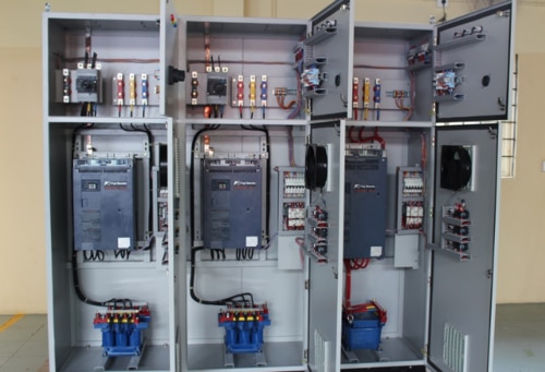
VFD Panel
VIEW DETAILS

UPS Input-Output Panel
VIEW DETAILS

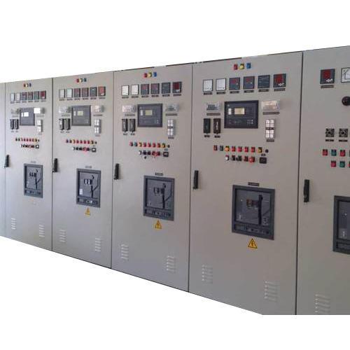
DG Synchronization panel
VIEW DETAILS
AMF Panel
VIEW DETAILS
APFC Panel / Power Factor Correction P
VIEW DETAILS
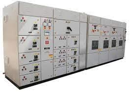
MCC Panel
VIEW DETAILS
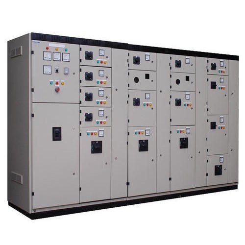
PCC Panel
VIEW DETAILS
Filter using tags
Motor Control Center PanelPower Control Center PanelPCC PanelPower Distribution PanelMain LT Power PanelMain LT PanelDG Synchronization panelLoad Management PanelAMF Cum Synchronization PanelDG Syn PanelParalleling PanelHybrid Paralleling PanelAuto Mains Failure PanelAMF PanelAMF ATS PanelPower Factor CompensationPassive FilterPower Factor CorrectionAPFCR PanelAPFC PanelSolar ACDB PanelSolar DCDB PanelSolar Distribution PanelSolar ACDB Combiner PanelSolar Outdoor Distribution PanelOperation Therater Isolation PanelOT PanelIsolation PanelHealthcare OT PanelHospital OT PanelFire Fighting PanelFire PanelEmergency Fire PanelHVAC PanelAHU PanelVentiliation PanelBasement Ventiliation PanelExhaust Blower Panel